


| 
|
Introduction
First things first: The links work again, I moved the stuff from wuala to onedrive.
Ok, first things first: I have an Arduino UNO wich is suited with an Atmega328p-Chip and so I thought I just order these. I use mostly Windows machines so all software is given in MS Windows format here.
Here is the pin setting on the chip after the Arduino bootloader is installed.
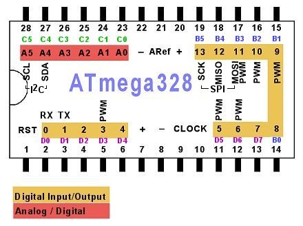 |
| stolen from: http://www.hobbytronics.co.uk/arduino-atmega328-pinout |
Parts List
Here is what you need:+ A computer. ;)
+ 1x Arduino UNO (or Duemilanove or something, try it out.)
+ 1x Atmega328 chip, DIP 28, brand new, with no bootloader or something on it.
+ A breadboard
+ 1x 10k Ohm resistor.
+ Some connections (wires) for the breadboard and arduino.
+ The Arduino IDE 1.0.1 or better. (Or maybe also worse but it did not work with IDE 1.0.0 !! It is because the software will use 9600 baud instead of 19200 if it is version 100. Even if I use explicitely 19200 baud in the sofware, it will not work.) You will find the newest version here: http://arduino.cc/en/Main/Software
(And here is my 1.0.1-mirror: arduino-1.0.1-windows.zip)
+ This mighty piece of software, wich will be uploaded on the host-Arduino. (To the Arduino UNO)
Download: ArduinoISP2c.zip
I do not know if it works with the internal clock, I just set all up like in the wiring below. Maybe you can spare the following parts:
+ 1x 16MHz crystal resonator
+ 2x 22pF capacitors
At last, the LEDs. You do not need them but they are very useful for fast detection of...stuff. ;)
+ 1x Blue LED wich represents the heartbeat of the host-software.
+ 1x Green LED wich represents succesfull transmission to the chip.
+ 1x Red LED wich represents errors or not-in-sync.
+ 1x Yellow LED wich is connected to (Arduino-)pin 8 on the breadboard-chip to test if it works.
+ 4x 100 Ohm resistors (for the LEDs, maybe you need other ones but 100Ohm suit the most LEDs for driving with the given 5V.)
Now, let's get started.
Setting up your Arduino
First, to upload software on the Arduino, please disconnect it from the breadboard. Just for the safety of the chip on the breadboard. To make that easier, we will upload the software to the Arduino just now. It is installed then and we do not need to worry about it again.+ Open the IDE. Select the right port in the Tools-Menu if it is not already set.
+ Upload the ArduinoISP2.ino file - wich you can download above - to your Arduino. You NEED to use another version than IDE 1.0.0 - see above.
+ To program the chip (on the breadboard), we need to select the right programmer in Tools->Programmer: It is "Arduino as ISP". Double check that. ;)
+ Now upload the sketch.
+ You can now connect the breadboard to the Arduino.
That's all for that.
Schematics:

Wiring on the breadboard:
--> Note that the 10k resistor should go to positive, not to ground. It's an error here, sorry.

Here you have the raw Fritzing file: atmegaprogrammer.fzz
Fritzing is an open-source software to "draw" wirings/schematics/pcb-designs. (http://fritzing.org)
Avrdude is included in the IDE somewhere. I downloaded it and put it into its own directory, though. It is a command line tool and I wrote some batch files to ease it up.
You can get avrdude (solo) here: avrdude-5.10.zip
You may need the WinAVR suite to get avrdude running properly.
http://winavr.sourceforge.net/
From there you need the file libusb0.dll wich is in the lib folder. Copy that to where your avrdude.exe is.
Using Avrdude
Avrdude is a command line tool where you have to give some parameters. It's almost the same with linux except that the path to the device is another. (here: com3, linux: ..../.../...)This are the parameters wich we will use here:
-c : choose the programmer. We will use avrisp.
-p : choose the chip to program. It's m328p here.
-P : the device port of the arduino. It's com3 on my machine.
-b : the baud-rate to use. It's 19200.
-U: do some command on the chip.
-u : I don't know. I needed it. It overwrites the lock or tells to ignore not-sync-errors or something like that. o.O. All we need to know is: It works with it, it does not without it.... ;)
Ok, first check if the chip is ready.
avrdude -c avrisp -p m328p -P com3 -b 19200
Something like "All Ok" should pop up in the console. If everything is OK, we will set the fuses. I don't know exactly what the setting "does", I only know it works. I had to get the value for the low-fuse manually but the other values are copied from another website.
The chip is set to run with the internal 8MHz oscillator. We will set it to external 16MHz quartz.
Also, the lock will be set to 0x0F and some other fuses like seen below.
Fuse Calculator: http://www.engbedded.com/fusecalc
avrdude -b 19200 -c avrisp -p m328p -P com3 -u -U efuse:w:0x05:m -U hfuse:w:0xD2:m -U lfuse:w:0xFF:m -U lock:w:0x0F:m
That's it. To check the fuses, you can use this:
avrdude -p m328p -P com3 -c avrisp -b 19200 -U hfuse:r:fusehigh.txt:s -U lfuse:r:fuselow.txt:s -F
That writes the values of the given stuff (here: hfuse, lfuse) in to the given text files. (here: fusehigh.txt, fuselow.txt)
Burn the bootloader
Now that all fuses are set, the chip is ok and using the external clock, and the IDE programmer is set to "Arduino as ISP", we can burn the bootloader to the chip on the breadboard. Just select "Tools->Burn Bootloader" in the IDE and wait some time. If nothing has gone wrong, you should now be able to upload Arduino-sketches to the chip on the breadboard.Change the blink-sketch. [later] (short: change pin 13 to pin 8)
Upload the blink-sketch to the chip on the breadboard. [later] (short: select "Upload via programmer")
Final Check:
The yellow LED should flash now.Hope that helped.
I feel it's an important note to tell you that the 10k resistor that goes from the ATMEGA328's reset pin to ground should actually go to positive. I spent two hours trying to figure out what was wrong with my code and sync, just to find out there was nothing wrong with them! When that resistor goes to negative, the chip is in constant reset. You have to pull the reset pin positive for the setup to work.
AntwortenLöschenOther than that, your tutorial was very helpful. Thanks!
Thanks for your comment, it's the first really useful comment on the whole blog, so thanks again. I will update the text but not the picture. Greetings, ben0bi
AntwortenLöschen